
Standard & Enhanced End Cap Systems
Quick Disconnect End Cap Installation
Vertical Picatinney End Cap
STANDARD & ENHANCED END CAP ASSEMBLY
*** WARNINGS **
Before removing or installing any part, ensure the firearm is UNLOADED with the SAFETY ENGAGED. Remove the source of ammunition. Check chamber and magazine-well to ensure the weapon is unloaded, and then CHECK AGAIN. Always check the system for rigidity & that nothing has come loose before use.
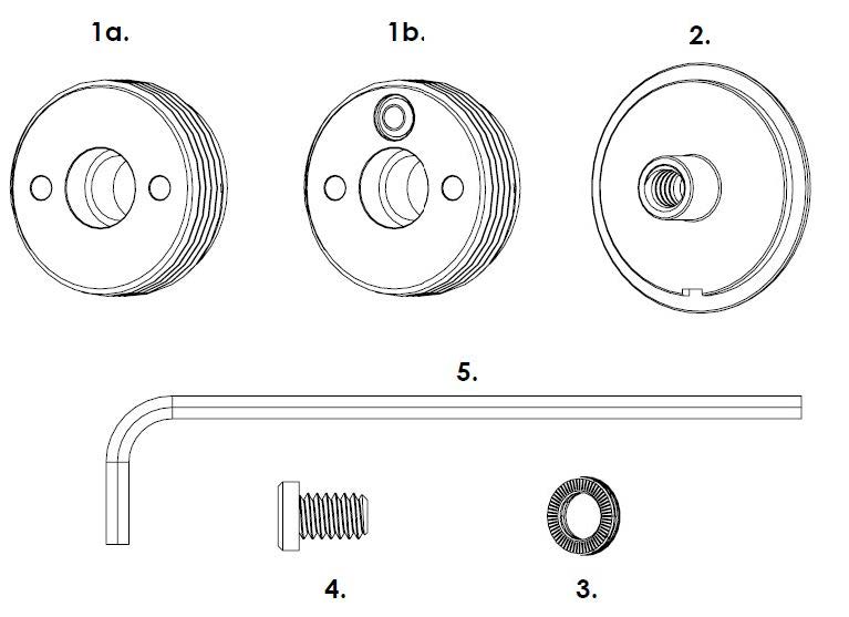
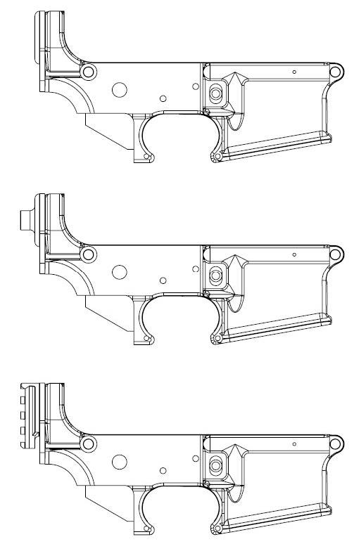
1a. Standard Base
1b. Enhanced Base
2. Blank End Cap
3. Lock Washer
4. Low Profile Screw
5. Installation Allen Key
1. PREPARE FOR INSTALLATION
Make sure you have proper eye and hand protection. Make sure you have a properly calibrated torque wrench and a new 1/8” Allen hex driver bit installed onto the torque wrench. Make sure all items from the parts list are present and the receiver you are going to install onto is ready.
2. REMOVE STOCK ASSEMBLY
Ensure the weapon is unloaded with the safety engaged! Remove the stock from the lower receiver, safely remove the buffer and action spring from the receiver extension a.k.a buffer tube (Careful to note the buffer, action spring, buffer retainer & buffer retainer spring are under compression and can pop out unexpectedly if not properly held and the spring load carefully relieved).
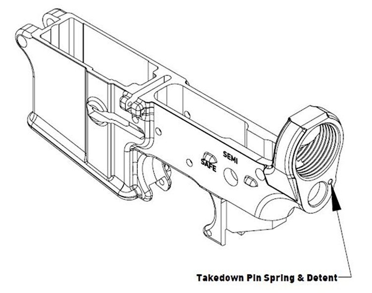
With all items removed you can remove the castle nut, receiver extension and receiver end plate (Careful to note, on Mil‐Spec style receivers the takedown pivot pin detent & spring are held in by the receiver end plate and are under compression). For detailed information on removing the stock assembly from the receiver, refer to the O.E.M. firearms manual or the US Army Maintenance Manual TM 9‐10050319023&P.
3. INSTALL BASE
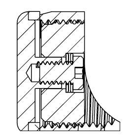
Take the Standard or Enhanced Base and slowly thread into the lower receiver from the rear by hand, adjustable spanner wrench or the Sensei Firearm Installation Tool. Make sure the counterbore is facing towards the Front (Where the muzzle is) and the non‐threaded portion is facing the rear (Where the Shooter Stands) Continue to thread until the front face of the base is flush with the inside face of the lower receiver.
4. INSTALL END CAP & END PLATE
Place the receiver end plate onto the matching groove of the End Cap, aligning the indexing notch of the End Cap with the Tab on the Receiver End Plate, and install the detent and spring of the takedown pin, per the original manufacturer’s of the firearms procedures and snap the End Cap with the Receiver End Plate onto the rear of the Receiver holding together to keep springs & detents in place.
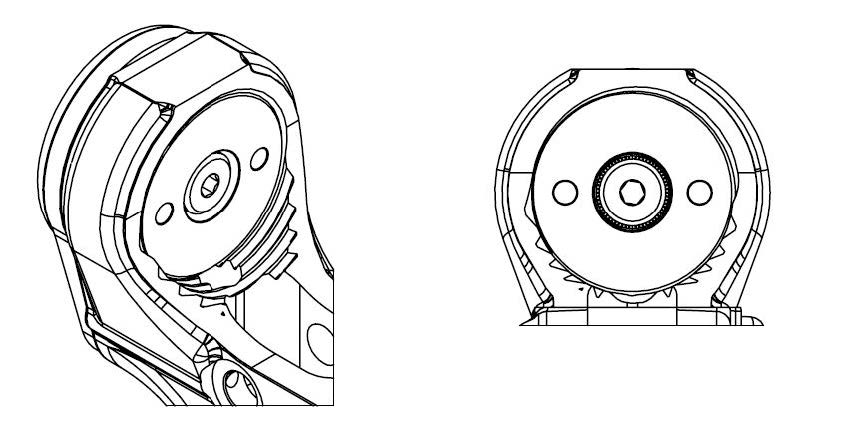
Using the included installation 1/8” Allen wrench from the front side of the receiver insert the Low‐Profile Screw with the Lock Washer thru the counterbore of the base into the End Cap threaded section. Slowly Tighten until the device is snug and all captured detent and springs are in place.
5. TEST TAKEDOWN PIN FUNCTION
With everything installed test takedown pin function per the original manufacturer’s procedures and specification.
6. FINALIZING INSTALLATION
If the Takedown pin is functioning correctly, place the upper receiver onto the lower receiver per the original manufacturer’s manual and test for dry function of the cycle.
If everything is functioning correctly using the 1/8” Allen hex bit and a calibrated torque wrench tighten the screw to the following specification:
| End Plate | Torque Spec |
|---|---|
| Blank End Cap | 5.5 ~ 6.5 ft‐lbs |
| QD & Vertical Picatinny End Cap | 6 ~ 7 ft‐lbs |
The lock washer is designed to lock into place when installed correctly and eliminate any possibility of allowing the low profile screw to back out. But it is recommended to inspect and re‐torque the screw every year in light to moderate use, quarterly if used in high usage and checked even more frequently if using daily. The lock washer is designed to be re‐used.
Note: Torque specifications are for “Dry Torque”. Blue Loctite can be used. DO NOT USE RED!